Efficient Electrocatalyst Utilization in Proton Exchange Membrane Fuel Cells
Electrochemical Deposition of Pt Nanoparticles Using Nafion® Membrane as a Template
Nafion® membranes are one of the most commonly used electrolytes in methanol and hydrogen fuel cells. Under operating conditions this membrane absorbs water and phase separates into hydrophobic and hydrophilic domains [1-4]. Migration of protons takes place through the hydrophilic domains. To produce electrical energy in a fuel cell, the hydrophilic domains must provide a continuous pathway from the anode to the cathode and also have a catalyst particle at both ends. Recently it has been shown that the Pt catalyst can be deposited electrochemically through the hydrophilic channels of the Nafion membrane [5]. This method places the catalyst only in the hydrophilic domains and avoids the waste resulting from Pt deposition under the hydrophobic regions of the membrane.

Figure 1. The ion-conduction channel model of a Nafion® membrane placed between two electrodes. The proton conducting hydrophilic channels are shown in white. The red and yellow spots represent catalyst particles in a conventional fuel cell. Particles in yellow are not used effectively. In our work, catalyst particles are deposited through commercially available Nafion membranes (117, 112, and 212) by electrochemical pulse deposition.
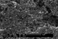
The size of the Pt nanoparticles can be carefully controlled by changing parameters such as pulse time delays (X and Y), the potential width, and the concentration of the electrolyte and pH of the medium. Active surface areas of Pt particles synthesized by this technique are determined by cyclic voltammetry (CV). Electrode surfaces are also investigated using Scanning Electron Microscopy (SEM) equipped with an Energy Dispersion Spectrometer (EDS) (Figure 2 ) .

Figure 2. SEM image of carbon cloth electrode after removing overlaying Nafion membrane, showing the presence of Pt particles that have been deposited through the membrane's hydrophilic channels.
References:
- Chu, Y. H.; Shul, Y. G.; Choi, W. C.; Woo, S.I.; Han, H. S. J. Power Sources, 2003, 118, 334-341.
- Paddison, S. J.; Paul, R.; Zawodzinski, Jr. T. A. J. Electrochem. Soc., 2000, 147, 617-626.
- Kanamura, K.; Morikawa, H; Umegaki, T. J. Electrochem. Soc., 2003, 150, A193-A198.
- Chou, J; McFarland, E. W.; Metiu, H. J. Phys. Chem. B, 2005, 109, 3252-3256.
- Chou, J.; Jayaraman, S.; Ranasinghe, A. D.; McFarland, E. W.; Buratto, S. K.; Metiu, H. J. Phys. Chem. B, 2006, 110, 7119-7121
Current Imaging of the Conducting Channels in Proton Exchange Membrane Fuel Cells
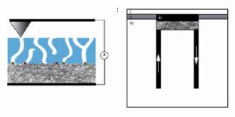
The electrochemically active area of a proton exchange membrane in an operating fuel cell is investigated using conductive probe atomic force microscopy. A platinum coated AFM tip functions as a nanoscale cathode as it scans the surface of a membrane, diagramed in Figure 1. This configuration allows investigation of individual proton conducting channels within the membrane, including their number, connectivity, and conductivity, properties critical to fuel cell performance.

Figure 1. Experimental apparatus consisting of Pt tip (cathode), which scans the surface of a proton exchange membrane hot-pressed to a carbon cloth electrode embedded with Pt particles (anode) and exposed to hydrogen gas. Shown at left is a side view of the fuel cell flow stage used for AFM scans, consisting of i) proton exchange membrane ii) insulating layer iii) Pt loaded carbon cloth (anode) iv) copper base. Arrows represent hydrogen gas flow at the anode.
Correlations and anti-correlations between hydrophilic surface domains and ion conductive channels were made by overlaying tapping mode and conductive AFM images taken on the same region of a given sample, shown in Figure 2. This comparison gives a direct measure of the electrochemical activity of each aqueous domain. We have found that a large number (~60%) of the aqueous domains present at the surface of a Nafion membrane are electrochemically inactive. We attribute this to a combination of limited aqueous domain connectivity and catalyst accessibility.

Figure 2. 1 um x 1 um AFM images of Nafion surface in the described fuel cell configurationa) TMAFM topography (z-scale 10 nm) b)TMAFM phase image (z-scale 15º) c)conductance image (z-scale 50 pA) d)Correlation image showing regions which contain both aqueous surface domains and proton conduction (maximum correlation in blue, minimum in black) e) Anti-correlation image showing regions which contain both aqueous domains and insignificant proton conduction (maximum anti-correlation in blue, minimum in black).
Initial work has focused on Nafion membranes (a perfluorosulfonic acid polymer) and commercially available electrode materials imaged under ambient conditions, while controlled variations in electrode fabrication and membrane preparation have also been explored. Changes in membrane water content and chemical structure may elucidate additional properties of the ion transport channels.
This project is supported by the Army Research Office Multi-University Research Initiative.
Related publications:
- Bussian, D. A.; O'Dea, J. R.; Metiu, H.; Buratto, S. K., Nanoscale Current Imaging of the Conducting Channels in Proton Exchange Membrane Fuel Cells. Nano Letters 2007, 7, 227-232.
- Gargas, D. J.; Bussian, D. A.; Buratto, S. K., Investigation of the connectivity of hydrophilic domains in nafion using electrochemical pore-directed nanolithography. Nano Letters 2005, 5, (11), 2184-2187.
- Chou, J.; Ranasinghe, A.; Shrisudershan, J.; McFarland, E. W.; Buratto, S. K.; Metiu, H., Efficient Electrocatalyst Utilization. Journal of Physical Chemistry B 2006, 110, 7119.
- Chou, J.; McFarland, E. W.; Metiu, H., Electrolithographic investigations of the hydrophilic channels in Nafion membranes. Journal of Physical Chemistry B 2005, 109, (8), 3252-3256.
